Here we will learn how to create our first project on the Blynk IoT platform. We will connect an LED to some pin on the NodeMCU. Then we will be able to controll it both through the blynk mobile app and the web portal through computers.
We will use NodeMCU throughout this tutorial. It is a WiFi capable Development Board based on the ESP8266 microchip.
- Account
- Templates
- Datastreams
- Setting up Web Dashboard
- Creating and Setting up Devices
- Coding
- Adding Libraries
- Making a basic LED control project
1. Account
First you have to go to the Blynk Site site, and make an account.
After you have logged in to your Blynk account, you will be able to see a dashboard like this:
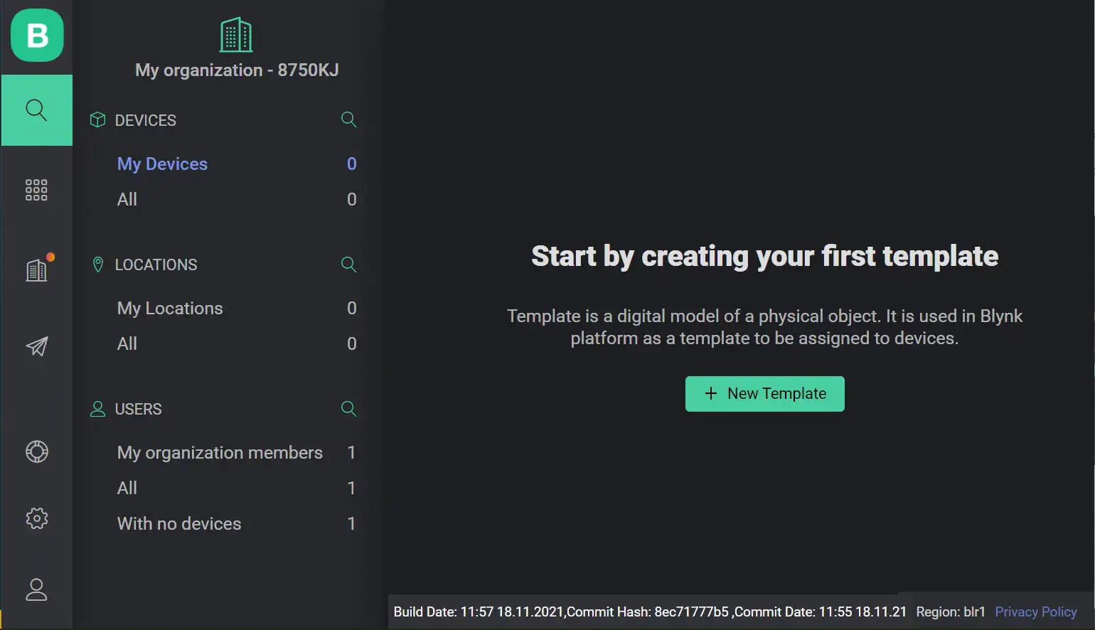
2. Templates
Before creating a device, you need to create a template.
What are Templates?
At first, you have to create a template for each type of device you have. For example, in this tutorial, we will control an LED through a button on your smartphone or laptop. At first we will make a template for a light, then we can make a device called light and tell that it belongs to this template.
Creating templates is somewhat like defining objects in programming and creating devices is like making instances of those objects. There can be multiple devices under the same template.
How to Create Templates?
To create a template, first click on the new template button on the dashboard and fill up the form. I am using a NodeMCU which is based on the ESP8266 microchip. So, I have put “Hardware = ESP8266”.
This is how mine looks:
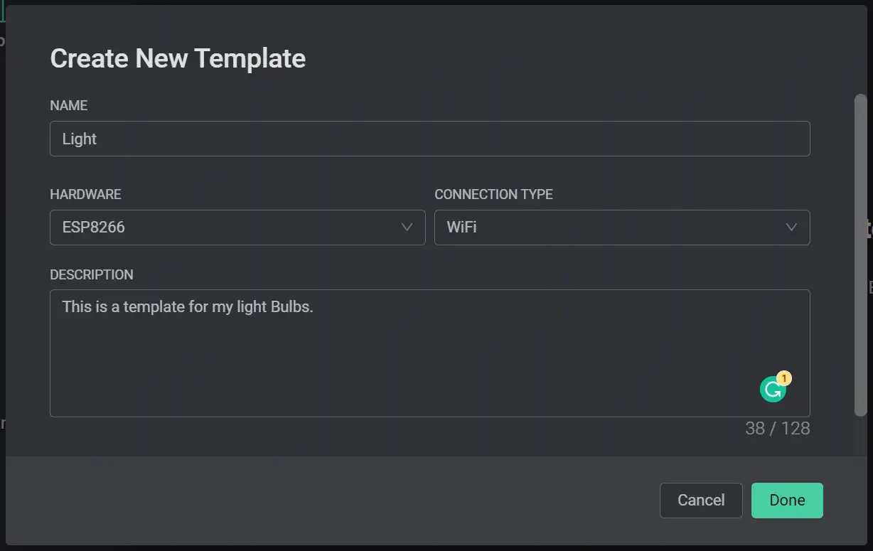
Finally click on button to create the template.
After creating the template, you will see something like this:
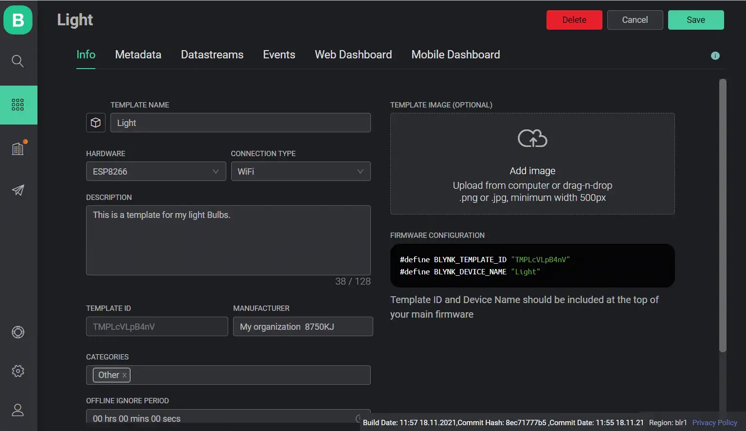
Under the Info tab, you can further edit the data you have just entered along with some other fileds.
Note that we are given 2 informations (BLYNK_TEMPLATE_ID and BLYNK_DEVICE_NAME) under this Info tab. We will need those two pieces of informations later. So, we will return to this Info tab again while writing the code.
Editing the Metadata tab is not essencial for device setup. So let us skip it and move on to the Datastreams tab.
3. Datastreams
According to Blynk: Datastreams is a way to structure data that regularly flows in and out from device. Use it for sensor data, any telemetry, or actuators.
What are Datastreams?
Datastreams are the channels of data that will be shared between the devices. There are various sorts of datastreams:
Digital and Analog Datastreams: Digital and Analog Datastreams are generally used to read data from the sensors. Setting up such a datastream might let you read temperature data from your device with a temperature sensor and view it on your smartphone. It might also be symultaneously used to automatically turn on the AC when the temperature reaches a certain value.
Virtual Pins: These pins do not have any physical existence. They are mere buttons or sliders on your smartphone/laptop screen which helps you to manually interact with these devices at your own will. Such a datastream will let you set up a virtual button on your smartphone whose value you can controll manually. Thus you can setup an LED to turn on when the value of that virtual pin is 1 and turn off when that is 0. We can avail 255 virtual pins in the Blynk IoT platform.
*Number of possible Digital and Analog Datastreams depends on the device you are using.
In this tutorial, we will concentrate on “Virtual Pins” only.
Setting up Virtual Pins
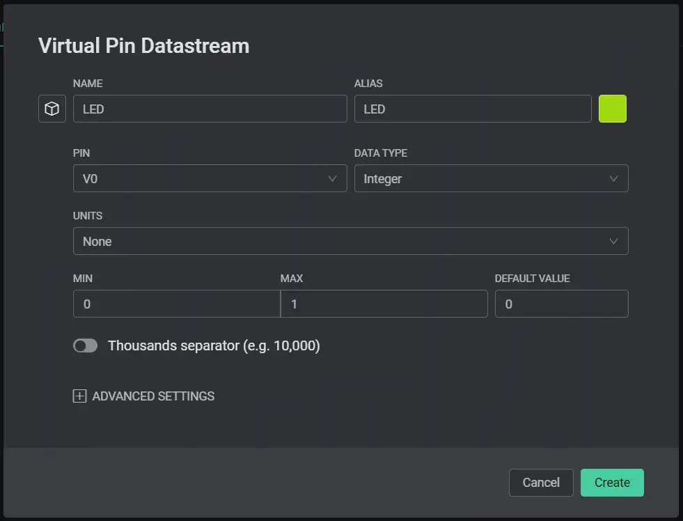
To setup a Virtual Pin, navigate to the Datastream tab, hover on the button and select Virtual Pin. Next, fill up the form.
I have taken Virtual Pin V0 (available V0-V255). Here we will controll an LED by reading the value from this pin. It has only two states (i.e.: on and off). So we will set datatype as Integer and set the minimum and maximum values to be 0 and 1. Default value is your choice!
Mine looks like this:
When done, click on button to create the datastream.
4. Setting up Web Dashboard
This is the dashboard you will be using to control your devices. Though the web dashboard and the app dashboard works exactly the same way, you will have to setup both of them separately. :(
Next move on to the Web Dashboard tab, drag and drop a switch in the working area (You might also like to add an LED which will show you the current state of the actual LED). You can resize the buttons.
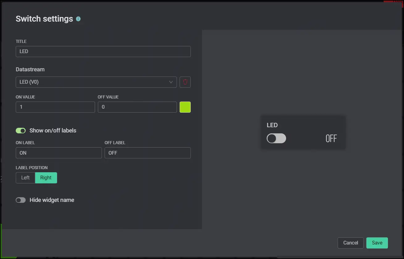
Finally click on the nut (settings) icon on the top left corner of the switch which you have just dragged and dropped onto your working area. Select the datastream you have just created and fill the rest of the informations according to your needs. Save it at the end.
I have filled it up like this:
If you have brought the LED to the workspace, which will show you the current state of the actual LED, you need to connect that to to the required datastream too (in my case V0). Click on the icon to do that.
This is how my Web Dashboard came up to be:
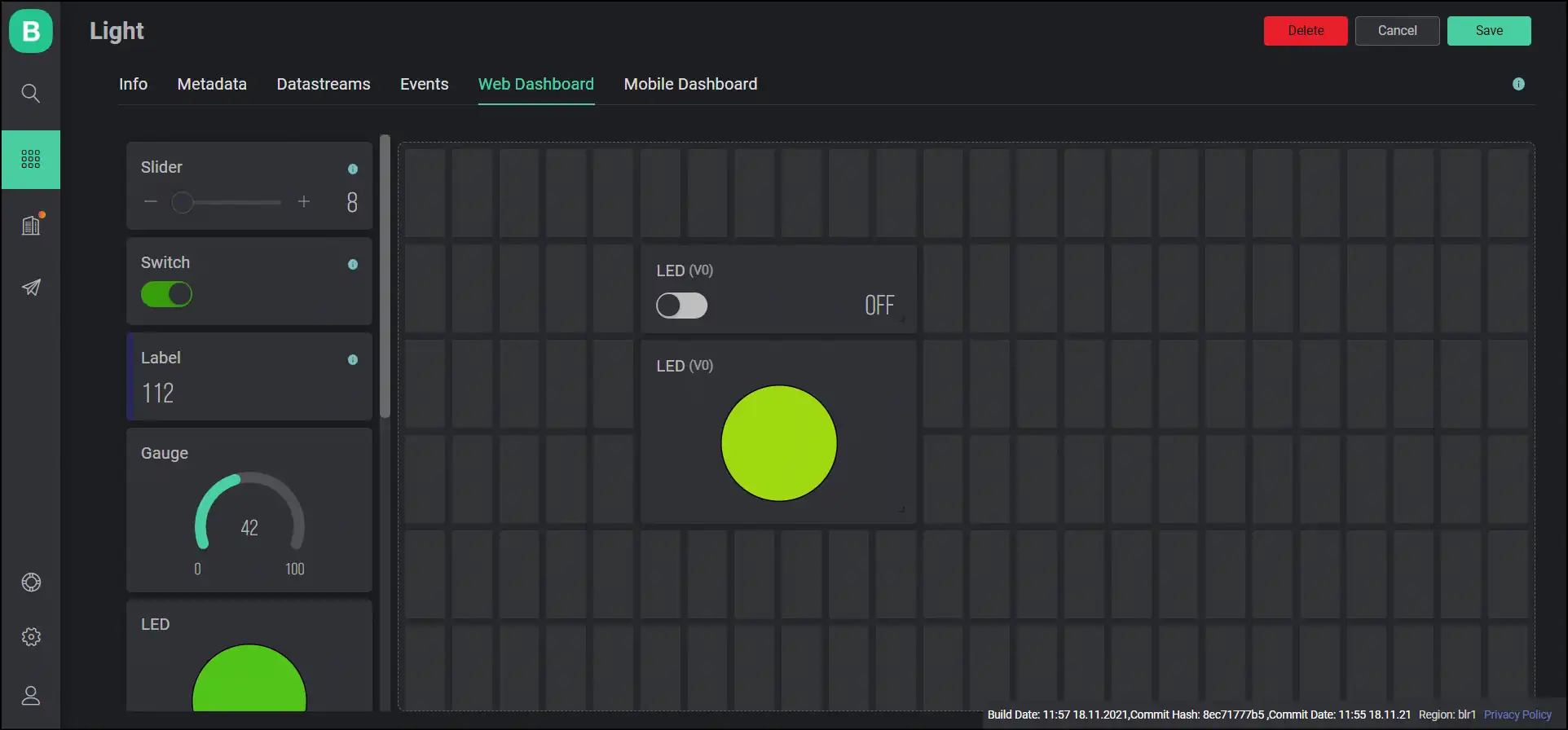
When you are done click on the top right.
Congratulations! Your template is ready!
5. Creating and Setting up Devices
Now that we have our template, we can create multiple devices from the same template. There are two ways of creating a device:
-
Through Mobile App: In this way, we won’t upload the WiFi connecting credentials in the Code of the NodeMCU. After uploading the code, we will (sort of) login to the NodeMCU through Blynk Mobile App and enter the WiFi credentials there. You need to keep only the BLYNK_TEMPLATE_ID and BLYNK_DEVICE_NAME in the code. You will get that in the Info tab of the template (as mentioned above). When the Blynk Mobile App connects to the device, it will automatically save the WiFi credentials and the Auth Token to the EEPROM of the NodeMCU. It will generate an Auth Token while creating a device.
-
Through Auth Token: The last method only worked with the help of Blynk Mobile App, but this process can be followed in both Mobile/PC. Here we will virtually create a device. Then we would be provided with an Auth Token. We would include Template ID, Device Name, Authorisation Token, WiFi SSID and, WiFi Password in our code. Then the device will work without any further setup through both the Blynk App and the web interface.
We will learn both the processes in detail. We will only learn the second method (Through Auth Token) now. We will learn the Mobile App method while learning how to use the app towards the end of this page.
Through Auth Token
Go to the search tab on the navigation bar on the left.
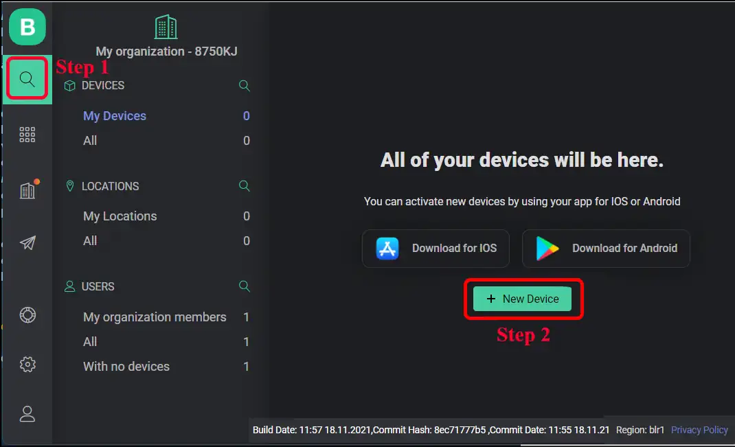
Then Click on button and select to add a device from Template (the other options are not for us). Select the template name and name the device. I will use a green LED. So I kept the name of my device as Green LED.
Now, on the top right corner, you will see a pop up like this:
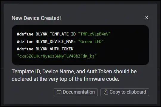
This contains all the informations which are needed to be put into the code apart from the WiFi credentials.
What? You clicked on the cross by mistake? Don’t worry, you can always find these informations under the Device Info tab.
Through Mobile App
We need to know about the code before setting up the device through MobileApp. So, please skip to here if you know the coding part. the top right.
6. Coding
We will complete the coding part in the Arduino IDE. At first, we need to install some libraries into it.
Installing Libraries
We would need to install ESP8266 Board and the Blynk Library in the Arduino IDE:
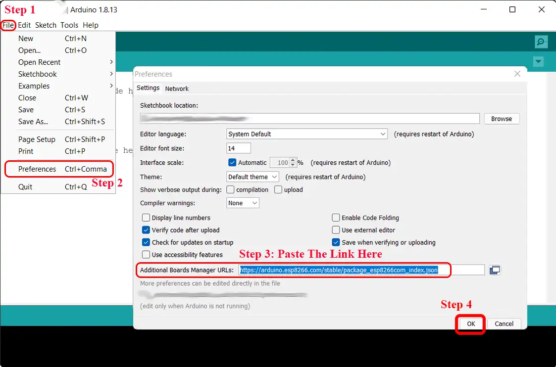
- ESP8266 Board: In the Arduino IDE, go to:
- File -> Prefferences -> Paste this link
http://arduino.esp8266.com/stable/package_esp8266com_index.jsonin Additional Boards Manager URLs field -> OK
…next in the Arduino IDE, go to:
- Tools -> Board: -> Board Manager… -> Search “ESP8266” -> install it -> Close it -> Again go to Tools -> Board: -> Select “NodeMCU 1.0 (ESP-12E Module)”
- Blynk Library: First click here ⬇ to download the code from this GitHub repository https://github.com/blynkkk/blynk-library as a .ZIP file.
Then in the Arduino IDE, go to:
- Sketch -> Include Library -> Add .ZIP Library… -> Select the downloaded .ZIP file -> Choose